Phoenix Evaluation Kit Quick Start Guide
Use this document to help setup and test your PX-01-EVK Phoenix Evaluation Kit.
Kit Contents
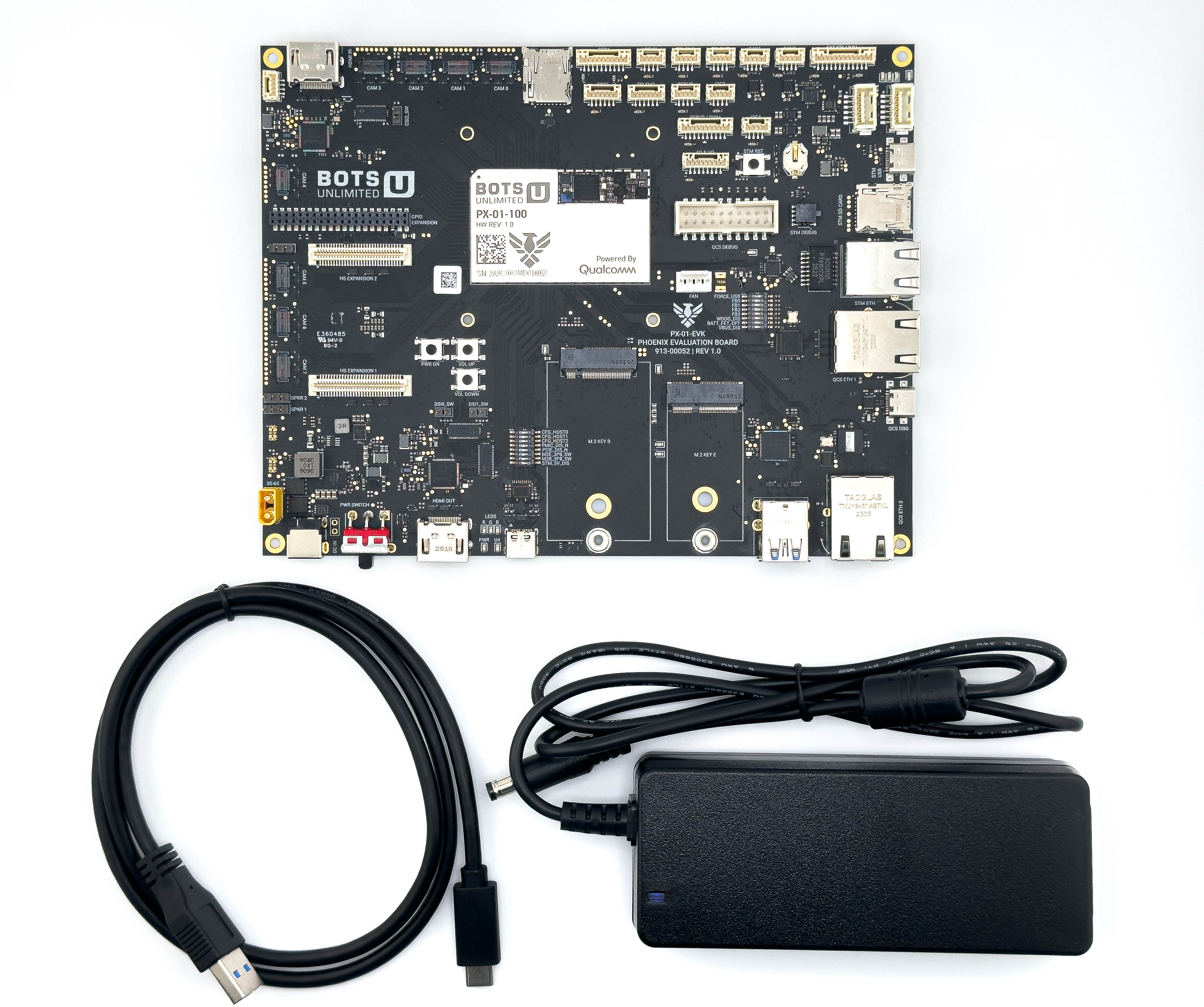
- PX-01-EVK Board
- 12V DC Power Adapter
- USB-C to USB-A 3.0 Cable
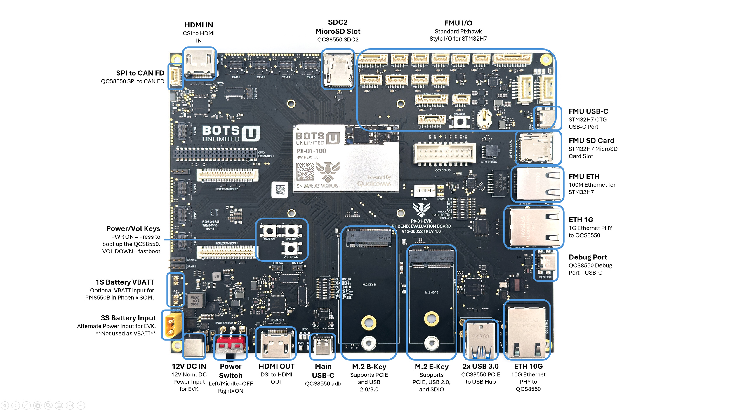
EVK Diagram
Hardware Quick Start
Note
Out of the box the EVK ships with a standard Ubunutu image pre-flashed. Fastboot/FORCE_USB modes are not required for the initial power up
-
Confirm All DIP Switches are Set Correctly
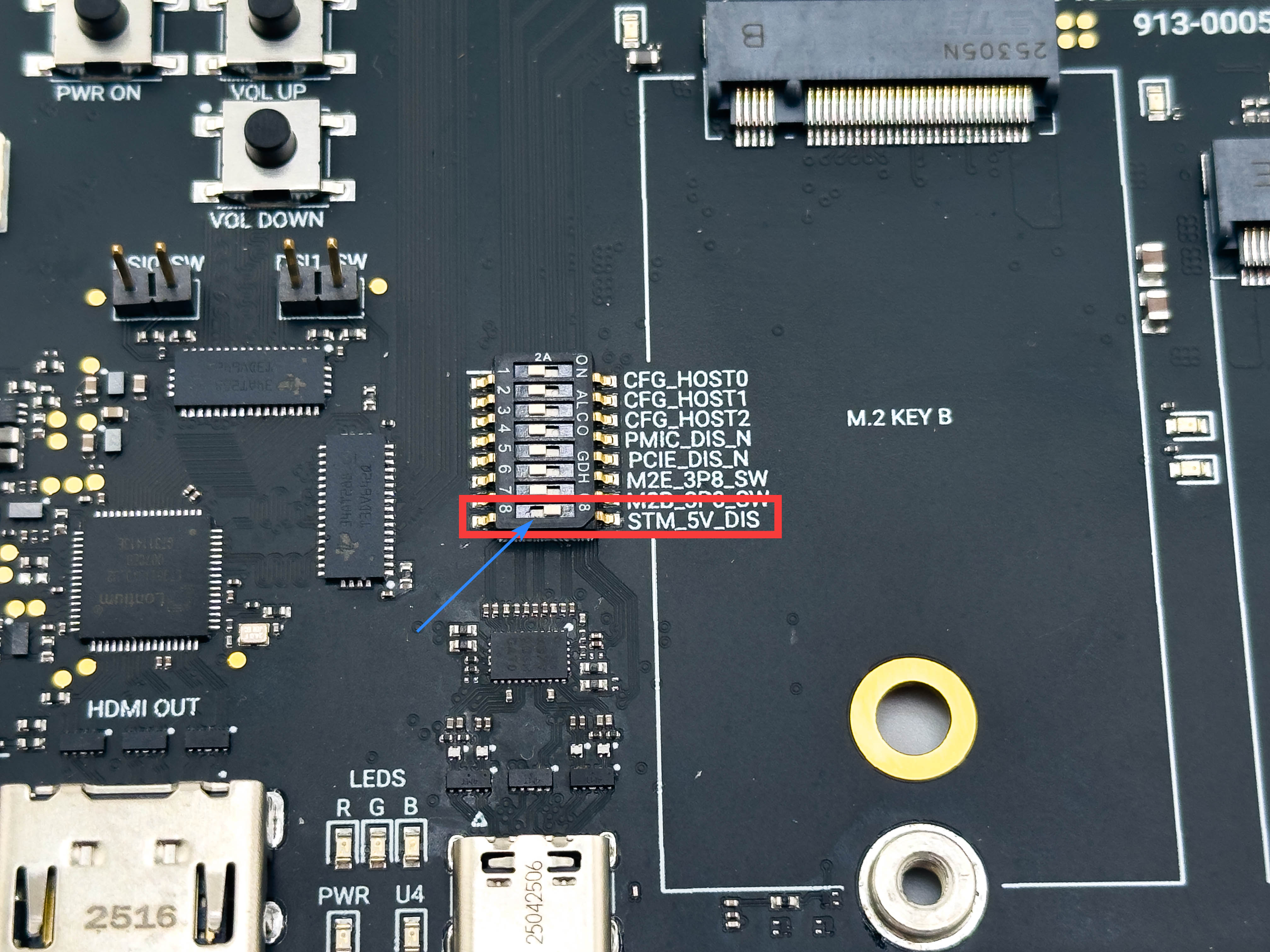
- EVK REV 1.0 ONLY - Ensure the STM_5V_DIS dipswitch is in the ON (right) position. If placed in the OFF position, the 5V regulator in the top right quadrant of the board will run excessively hot. This has been corrected in EVK REV 1.1.
- Since the EVK comes pre-flashed, standard boot modes can be used, so FASTBOOT, FORCE_USB, etc are not needed.
Warning
For EVK REV 1.0 ONLY - Ensure the STM_5V_DIS dipswitch is in the ON (right) position.
-
Power In
- Connect the 12V power adapter to the barrel jack
-
Power Switch
- Move the red slide switch labeled "PWR SWITCH" to the right most position. You should see LEDs come on to signal power on.
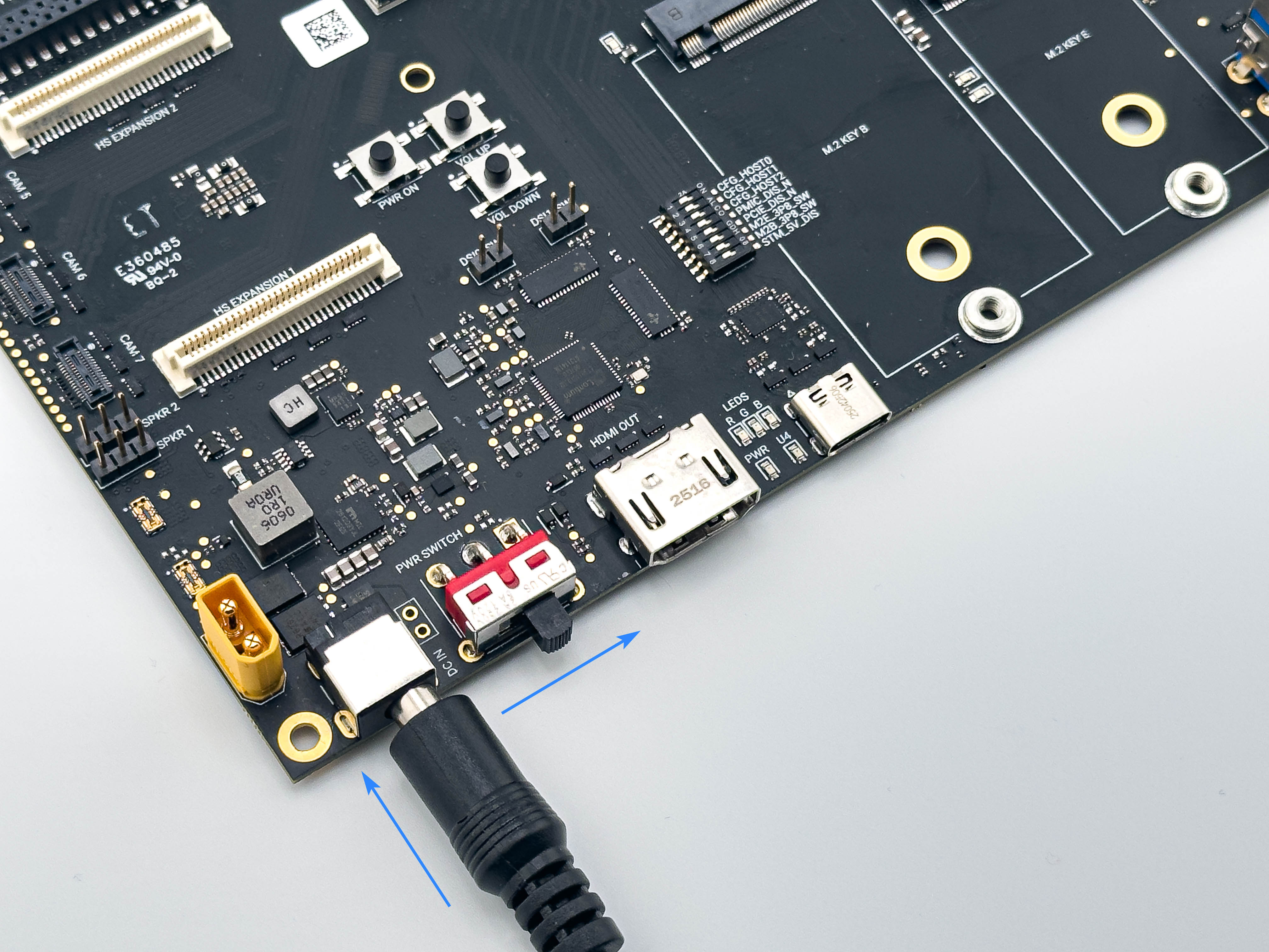
- Move the red slide switch labeled "PWR SWITCH" to the right most position. You should see LEDs come on to signal power on.
-
Connect Main USB-C Cable to Host Machine
- The "Main USB-C" port is configured by default for adb/fastboot. For debug, the Debug USB-C port can be used as well.
- The QCS8550 will start to boot as soon as the primary USB-C is connected to the host machine.
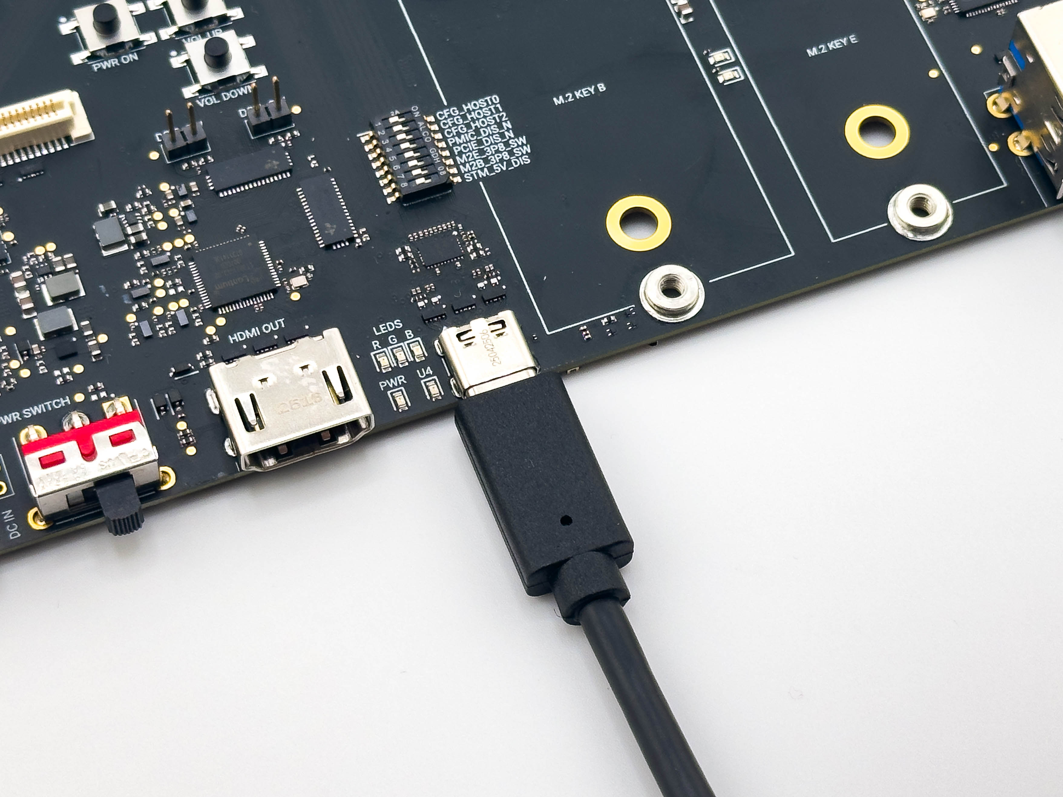
Warning
The USB-C by default is configured to supply power to the board. However, most USB ports cannot supply enough power and the EVK will not boot correctly. Please ensure that DC power is supplied via the barrel jack or XT30 connector AND the slide switch is in the ON position prior to connecting the USB-C cable.
DIP Switch Options
M.2 DIP Switches
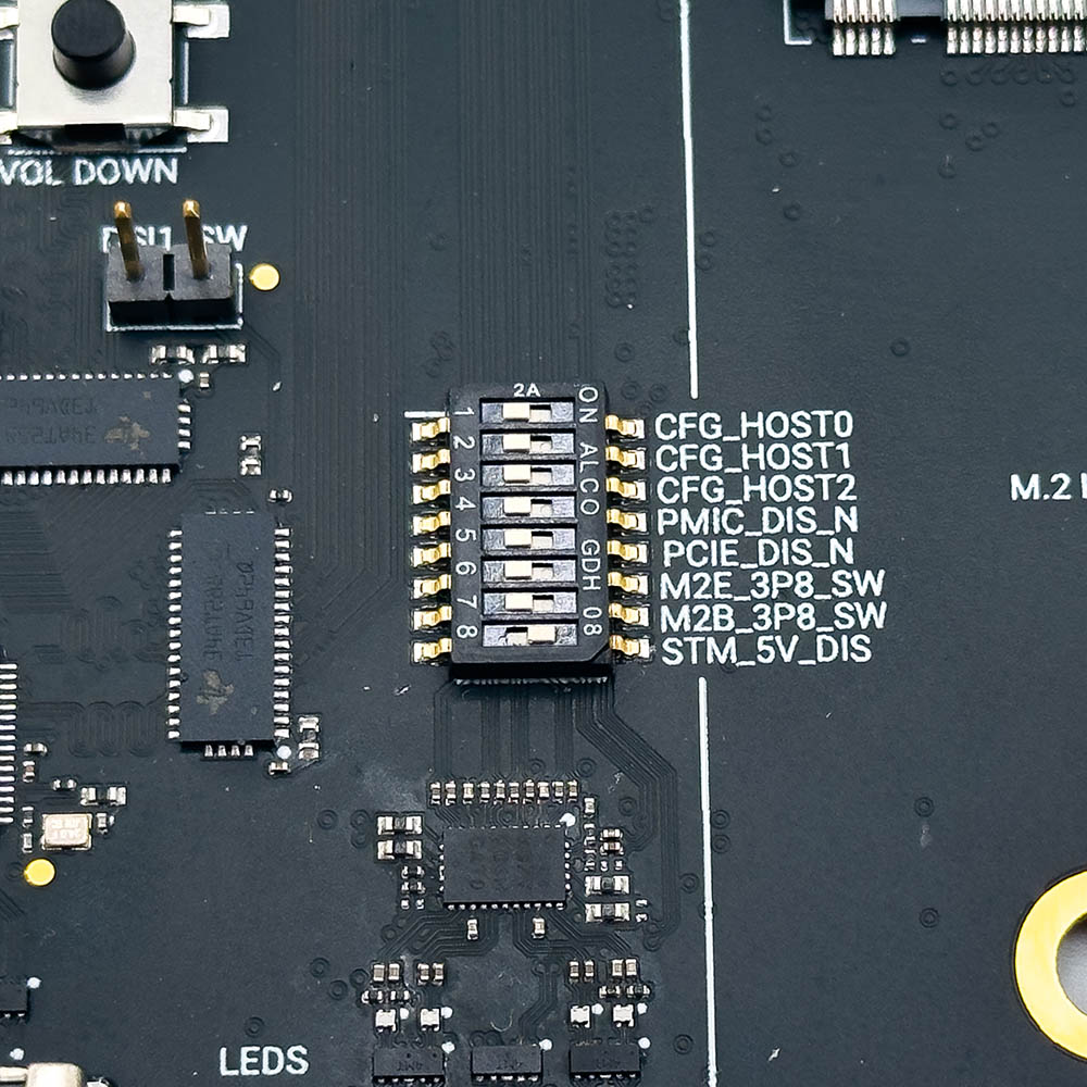
| Switch Number | Name | Description |
|---|---|---|
1 |
CFG_HOST0 | VENDOR DEFINED Strapping Pin for M.2 E-Key. Used for Sparrow Module configuration. |
2 |
CFG_HOST1 | VENDOR DEFINED Strapping Pin for M.2 E-Key. Used for Sparrow Module configuration. |
3 |
CFG_HOST2 | VENDOR DEFINED Strapping Pin for M.2 E-Key. Used for Sparrow Module configuration. |
4 |
PMIC_DIS_N | W_DISABLE2 Control for M.2 E-Key. Used for Sparrow Module power down. |
5 |
PCIE_DIS_N | W_DISABLE1 Signal for M.2 E-Key. Standard PCIE Disable control. |
6 |
M2E_3P8_SW | Controls the primary M.2 E-Key supply voltage to the edge card. OFF=3.3V ON=3.8V |
7 |
M2B_3P8_SW | Controls the primary M.2 B-Key supply voltage to the edge card. OFF=3.3V ON=3.8V |
8 |
STM_5V_DIS | Used to disable the STM32 5V regulator for the SOM. For REV1.0 EVK, DO NOT USE. |
Boot Mode DIP Switches
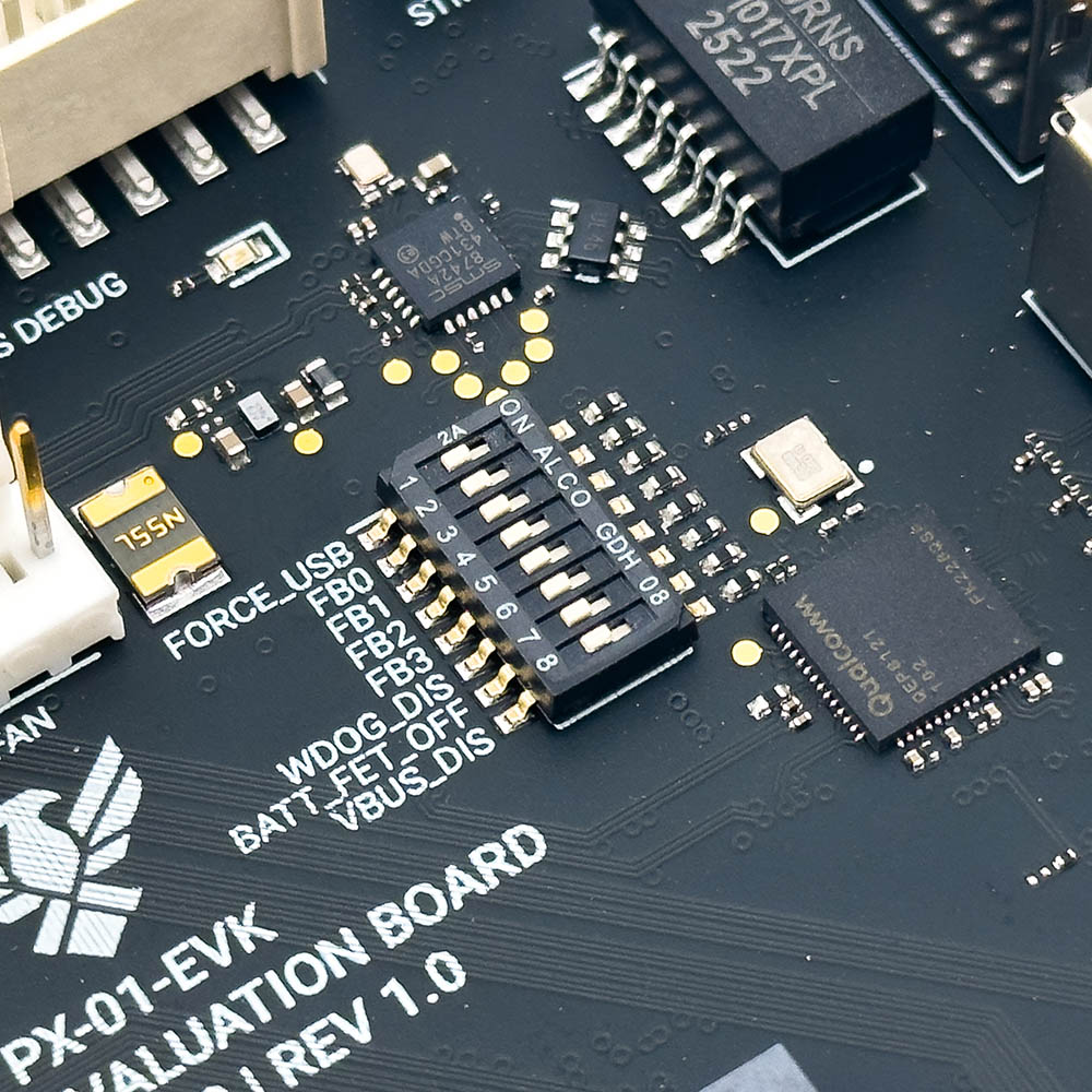
| Switch Number | Name | Description |
|---|---|---|
1 |
FORCE_USB | FORCE_USB mode enable. Sliding to ON will place the EVK in EDL mode. |
2 |
FB0 | FASTBOOT[0] pin control. See table below for config options. |
3 |
FB1 | FASTBOOT[1] pin control. See table below for config options. |
4 |
FB2 | FASTBOOT[2] pin control. See table below for config options. |
5 |
FB3 | FASTBOOT[3] pin control. See table below for config options. |
6 |
WDOG_DIS | Disables the QCS8550 watchdog - used for debugging. |
7 |
BATT_FET_OFF | Used to control the connection between VBATT and the physcial battery pack. |
8 |
VBUS_DIS | Used to disable VBUS connection from primary USB-C to PM8550B on the SOM. |
FASTBOOT Config Options
| FASTBOOT[3:0] | Boot Sequence |
|---|---|
0000 |
UFS -> USB(SS/HS/FS) on Primary USB-C |
0001 |
SD -> USB(SS/HS/FS) on Primary USB-C |
0010 |
QPSI NOR -> USB(SS/HS/FS) on Primary USB-C |
0011 |
SPI NOR -> USB(SS/HS/FS) on Primary USB-C |
0100 |
UFS -> USB(SS/HS/FS) on Primary USB-C |
0101 |
USB(SS/HS/FS) on Primary USB-C |
0110 |
Unused/Reserved |
0111 |
Unused/Reserved |
Software & Driver Setup
ADB / Fastboot Setup
The Phoenix EVK uses Android Debug Bridge (ADB) and Fastboot for shell access, file transfer, log collection, software flashing, and debugging.
Install ADB and Fastboot
sudo apt update
sudo apt install -y android-tools-adb android-tools-fastboot
Download the official Android Platform Tools package from Google:
https://developer.android.com/tools/releases/platform-tools
Extract the ZIP file and open a Command Prompt inside the extracted folder.
Verify Installation
Run the following command:
adb version
You should see output similar to:
Android Debug Bridge version x.x.x
Connect to the EVK
- Ensure the EVK is powered using the included 12V adapter and power switch is in the ON (right) position.
- Connect the Main USB-C port on the EVK to the host computer.
- Allow the EVK several seconds to fully boot.
Run:
adb devices
Expected output:
List of devices attached
xxxxxxxx    device
If the device does not appear:
- Verify the USB-C cable supports data transfer
- Confirm DC power is connected to the EVK
- Try reconnecting the USB cable
- Verify the EVK completed boot successfully
Opening a Shell
To open a shell session on the Phoenix EVK:
adb shell
You should now have terminal access to the embedded Linux system.
Example:
sh-5.1$
Root Access
To restart ADB with root privileges enabled:
adb root
The ADB daemon will restart with elevated permissions.
After the daemon restarts, reconnect to the shell:
adb shell
You should now have a root shell.
Example:
sh-5.1#
Common ADB Commands
Push a File to the EVK
adb push myfile.txt /home/qcom/
Pull a File from the EVK
adb pull /home/qcom/log.txt
Reboot the EVK
adb reboot
View Kernel Logs
adb shell dmesg
View Live System Logs
adb logcat
Ethernet Networking
The Phoenix EVK supports Ethernet networking through the onboard RJ45 interface.
To check network interfaces:
ip addr
To test connectivity:
ping 8.8.8.8
Serial Debug Console
For lower-level boot debugging, the EVK includes a dedicated Debug USB-C interface.
This interface provides access to the Qualcomm debug UART and can be used for:
- Bootloader logs
- Kernel boot logs
- Recovery/debugging
- Fastboot troubleshooting
Ubuntu Example Using screen
Install screen:
sudo apt install screen
Open the serial console:
screen /dev/ttyUSB0 115200
To exit screen:
CTRL+A then K
Fastboot Mode
The Phoenix EVK supports Qualcomm FASTBOOT boot modes for software flashing and recovery.
Entering Fastboot Mode
- Ensure the EVK is powered using the included 12V DC power adapter.
- Move the red slide switch to the ON (right-most) position.
- Press and hold the VOL- button on the EVK.
- While continuing to hold the VOL- button, connect the Main USB-C cable to the host computer.
- Continue holding the VOL- button for several seconds after USB insertion.
Once the EVK enters FASTBOOT mode, run:
fastboot devices
Expected output:
xxxxxxxx fastboot
You can then flash images or perform recovery operations using standard fastboot commands.
Let’s build boldly —
The Bots Unlimited Team